Startup Is Not Commissioning
Startup proves that the equipment can run. Commissioning proves that the system was installed, configured and tested properly.
Those are not the same thing.
A newly installed air conditioner may start immediately, produce cool supply air and satisfy the thermostat during a short test. That does not confirm that airflow is correct, the refrigerant charge is accurate, the condensate drain works under real operating conditions or the system can perform properly during an Ontario heat wave.
Peak summer conditions expose weak installations quickly. A system that appears acceptable on a mild day may develop high-pressure faults, frozen coils, humidity complaints, water leaks or compressor problems once outdoor temperatures rise and runtime increases.
A proper AC commissioning checklist gives technicians a repeatable process. It replaces assumptions with measurements and catches installation problems before they become service calls.
The exact procedure will vary by manufacturer and equipment type, but every residential or commercial air conditioning commissioning process should confirm the same basic areas:
- Equipment compatibility
- Mechanical installation
- Indoor airflow
- Air distribution
- Refrigerant charge
- Electrical performance
- Condensate drainage
- Thermostat and control operation
- Delivered cooling performance
- Final documentation
The order matters. Refrigerant readings, temperature splits and equipment pressures can all be misleading when airflow or control settings have not been verified first.
1. Confirm the Installed Equipment
Before connecting gauges or taking operating measurements, confirm that the installed equipment matches the approved system design.
Record the model and serial numbers of the outdoor unit, evaporator coil, furnace or air handler, thermostat and any communicating controls. Verify that the indoor and outdoor components are an approved match and that the correct metering device has been installed.
This step is frequently treated as paperwork. It is not.
An incorrect indoor coil can affect capacity, refrigerant performance and efficiency. A furnace may have sufficient heating output but lack the blower range required for the selected cooling system. A replacement outdoor unit may have been connected to an existing coil without confirming compatibility.
Commissioning cannot correct an equipment-selection problem that was built into the project.
The initial equipment check should confirm:
- Outdoor-unit model and capacity
- Indoor-coil or air-handler model
- Furnace blower capability
- Refrigerant type
- Metering-device type
- Approved equipment match
- Required cooling airflow
- Electrical requirements
- Thermostat compatibility
- Number of cooling stages
- Manufacturer-required control settings
Also confirm the designed application. A system selected for a small residential replacement cannot be evaluated the same way as a multi-zone system, a commercial split system or a rooftop unit.
2. Inspect the Installation Before Startup
Do not begin with the refrigeration circuit. Start with the physical installation.
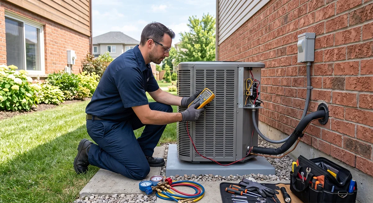
Inspect the outdoor unit for shipping damage, bent fins, loose panels, blocked coil surfaces and packaging material left inside the cabinet. Confirm that the unit is level, stable and installed with the required service and airflow clearances.
The outdoor location should allow the condenser to reject heat without pulling its own discharge air back through the coil. Enclosures, decks, walls, landscaping and adjacent equipment can all create recirculation problems.
Check the refrigerant lines for:
- Correct sizing
- Proper support
- Complete insulation
- Protection from physical damage
- Unnecessary contact with framing or sheet metal
- Sharp bends or crushed sections
- Oil traps where specifically required
- Proper sealing at wall penetrations
At the indoor equipment, inspect the coil cabinet, supply transition, return connection and access panels. Confirm that the filter is installed correctly and that temporary construction filters or packaging have been removed.
Also verify that:
- Service valves are fully open
- Valve caps are installed and tightened correctly
- Field wiring is secured
- Low-voltage wiring is protected
- Drain connections are complete
- Supply and return plenums are sealed
- The evaporator coil is clean
- The condenser coil is unobstructed
- Disconnects are accessible
- Equipment panels are installed
A five-minute visual inspection can prevent an hour of unnecessary diagnostic work.
3. Verify Indoor Airflow First
Airflow must be verified before the refrigerant charge is adjusted.
This is one of the most important rules in air conditioning commissioning, and it is also one of the most commonly skipped.
Low airflow can create refrigeration readings that resemble an undercharged system. Excessive airflow can reduce moisture removal and create comfort complaints even when the space reaches the thermostat setpoint.
Changing the refrigerant charge before confirming airflow can turn one problem into two.
Start by checking the filter, indoor coil, blower settings, return duct, supply duct, registers, dampers and any installed accessories. Confirm that the blower is configured for the required cooling airflow.
A selected blower tap or programmed airflow setting does not prove that the system is delivering the expected volume. Actual airflow is affected by the resistance of the entire duct system.
Measure total external static pressure where appropriate and compare the result with the manufacturer’s blower-performance data.
The airflow evaluation may need to account for:
- Filter resistance
- Return-duct resistance
- Supply-duct resistance
- Evaporator-coil pressure drop
- Electronic air cleaners
- Media filters
- Humidifiers or dehumidifiers
- Zone dampers
- Restrictive registers
- Undersized return grilles
Do not apply one universal static-pressure limit to every furnace or air handler. Acceptable operating conditions depend on the equipment, blower, coil and accessories.
When airflow is estimated using manufacturer tables, document the total external static pressure, blower setting and equipment configuration used to calculate it.
4. Check Air Distribution Through the Building
Correct total airflow does not guarantee correct room-by-room performance.
Walk through the occupied space and inspect the supply registers and return grilles. Confirm that they are open, unobstructed and properly balanced. Listen for excessive air noise, whistling filters and unstable zone dampers.
Upper-floor cooling complaints are common in Ontario homes, particularly during periods of strong solar gain. That does not automatically mean the air conditioner is undersized.
The actual cause may be:
- Poor duct balancing
- Excessive attic heat gain
- Limited return-air pathways
- Closed bedroom doors
- Duct leakage
- Long or restrictive branch runs
- Incorrect blower operation
- Poor thermostat placement
- Inadequate zoning
- Uninsulated ductwork in hot spaces
A commissioning technician should distinguish between a cooling-capacity problem and an air-distribution problem.
Increasing equipment size will not correct a poorly balanced duct system. Increasing blower speed may also make the system louder without delivering more air to the rooms that need it.
For zoned systems, test different zone combinations. A system may operate acceptably with all zones open but create excessive static pressure when only one small zone is calling.
Check bypass dampers, discharge-air sensors and minimum zone sizes where applicable. Variable-speed equipment still requires a duct system capable of handling the equipment’s operating range.
5. Verify the Refrigerant Charge Correctly
Do not charge an air conditioner by suction pressure alone.
Do not add refrigerant because the suction line does not feel cold enough.
Do not assume that the factory charge automatically covers the installed line-set length.
The correct charging procedure depends on the equipment design, refrigerant type, metering device, indoor load, outdoor conditions and manufacturer instructions.
Depending on the system, commissioning may require:
- Subcooling
- Superheat
- Weighed charge
- Manufacturer charging charts
- Line-set charge adjustments
- Dedicated test mode
- Forced cooling operation
- Electronic commissioning software
Before evaluating refrigerant charge, confirm that airflow is correct, both coils are clean, the metering device is correct and the system has been allowed to stabilize.
Record the indoor and outdoor conditions under which the readings were taken. Useful data may include:
- Outdoor ambient temperature
- Return-air dry-bulb temperature
- Return-air wet-bulb temperature
- Supply-air temperature
- Suction pressure
- Liquid pressure
- Suction-line temperature
- Liquid-line temperature
- Calculated superheat
- Calculated subcooling
Use the procedure specified for the actual model. A target taken from a different brand or equipment family is not a reliable reference.
Variable-capacity and inverter systems require additional care. The compressor may reduce speed as the space approaches the thermostat setpoint. Pressures, line temperatures and electrical current can change while measurements are being taken.
Use the manufacturer’s commissioning mode or forced-capacity procedure when required. Otherwise, the technician may be evaluating the system while it is actively changing output.
The goal is not to produce a familiar-looking gauge reading. The goal is to confirm that the system is operating according to its own published data.
6. Check Electrical Performance Under Load
Electrical checks should be completed before startup and again while the system is operating.
Confirm that the equipment voltage matches the installation and remains within the manufacturer’s allowable range. Take readings under load rather than relying only on an unloaded voltage measurement.
Inspect:
- Conductor sizing
- Breakers or fuses
- Disconnects
- Grounding
- Terminal tightness
- Contactor condition
- Wire routing
- Low-voltage connections
- Signs of overheating
- Damaged insulation
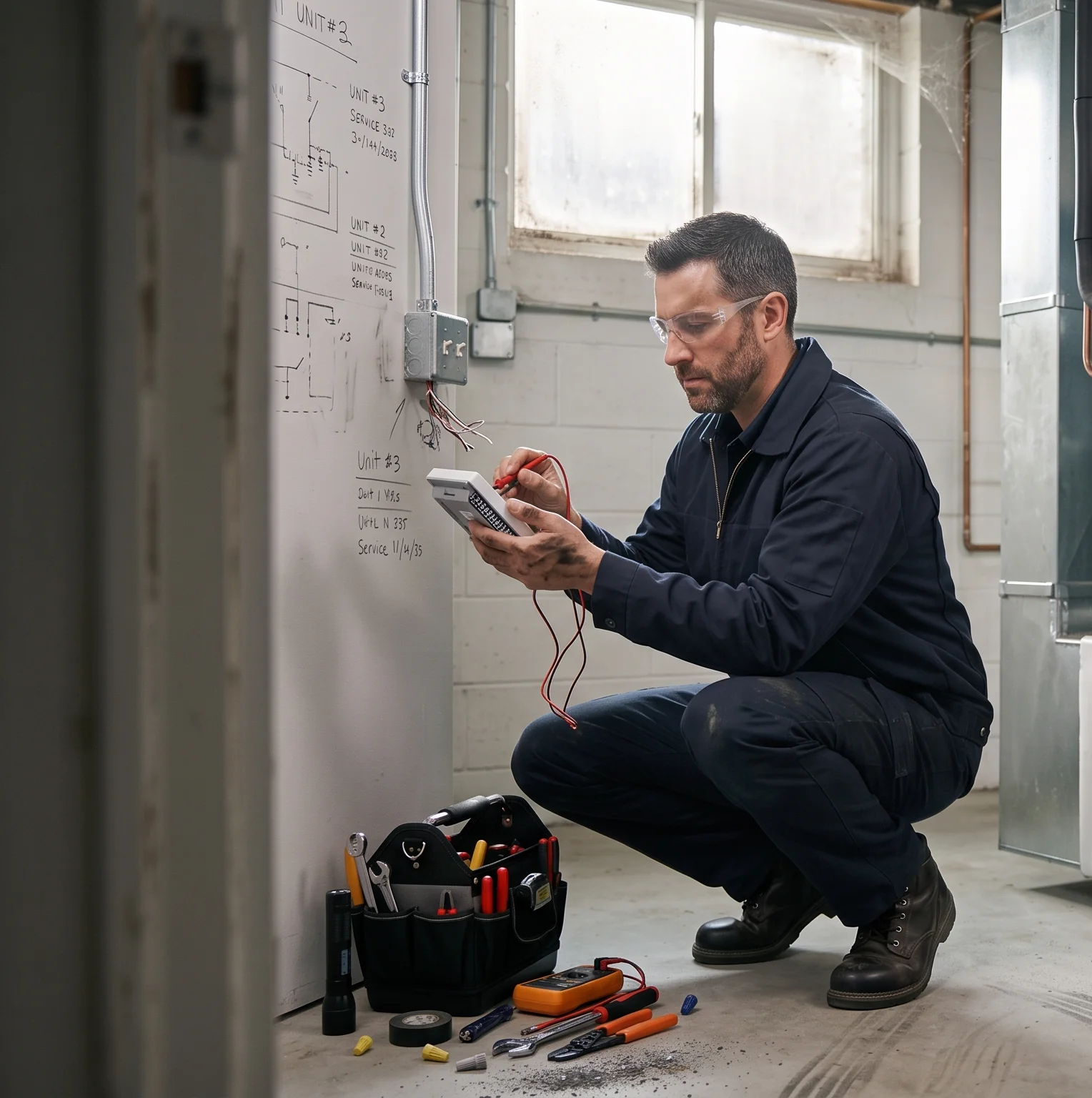
Record the operating current of major components where appropriate. This may include the compressor, condenser fan motor and indoor blower motor.
Compare measured values with the equipment data while considering the actual operating mode. A variable-capacity system running at reduced output will not draw the same current as it would under full-load operation.
Electrical readings must be interpreted together with refrigerant, airflow and control data.
High current may indicate excessive load, poor condenser airflow, abnormal refrigerant conditions or an electrical problem. Low current may indicate reduced inverter operation, incorrect staging or insufficient system output.
A number without operating context is not useful commissioning data.
7. Measure Delivered Cooling Performance
A temperature split is useful, but it does not prove that the system is fully commissioned.
The common expectation that every air conditioner should produce an exact 20°F temperature difference ignores indoor humidity, airflow, entering-air temperature, equipment type and compressor capacity.
Measure return and supply conditions using properly positioned instruments. Avoid taking a supply reading directly above the coil or from one register that may not represent the system.
Record:
- Return-air dry-bulb temperature
- Supply-air dry-bulb temperature
- Indoor relative humidity or wet-bulb temperature
- Outdoor temperature
- Thermostat setpoint
- Cooling stage
- Compressor operating capacity
- Runtime before measurement
Indoor humidity affects how the system divides its capacity between lowering air temperature and removing moisture.
During humid Ontario summer conditions, a significant portion of the system’s work may be latent cooling. That can produce a smaller dry-bulb temperature change even when the system is removing substantial moisture.
A larger temperature difference is not automatically better either. It may indicate low airflow, a dirty coil or another restriction.
Evaluate all readings together.
The system should operate steadily, deliver reasonable cooling for the current load and provide adequate moisture removal without unnecessary short cycling.
8. Evaluate Humidity Control
Temperature alone does not define indoor comfort.
A space can reach the thermostat setpoint and still feel uncomfortable when humidity remains high. This is especially noticeable in basements, tightly constructed homes, buildings with high outdoor-air loads and systems that cycle off quickly.
Check whether the equipment is running long enough to remove moisture. Review blower settings, thermostat configurations and any available dehumidification controls.
Common causes of poor summer humidity control include:
- Oversized cooling equipment
- Excessive blower airflow
- Continuous fan operation
- Incorrect staging
- Short cycling
- High outdoor-air ventilation
- Duct leakage
- Poorly sealed return ducts
- Improperly configured variable-speed controls
Continuous blower operation can re-evaporate moisture from the indoor coil after the compressor stops. That setting may need to be adjusted depending on the equipment and application.
Do not promise humidity performance without measuring the actual indoor conditions.
9. Test Condensate Drainage During Operation
A cooling system can appear to operate normally while water is collecting where it should not.
Inspect the primary drain connection, trap, vent, slope, fittings, insulation and termination point. Confirm that the installation follows the equipment requirements and local application.
A drain that flows when water is poured into the pan may still fail while the blower is operating. Negative pressure at the drain connection can interfere with drainage when trapping or venting is incorrect.
Check for:
- Standing water in the drain pan
- Leaking fittings
- Missing or incorrect traps
- Insufficient drain slope
- Unsupported drain piping
- Blocked cleanouts
- Uninsulated cold surfaces
- Condensate pump noise
- Pump short cycling
- Functional overflow protection
Test condensate pumps and safety switches rather than assuming that new components work.
For attic installations or equipment located above finished areas, secondary drainage and overflow protection are critical. A minor commissioning mistake can lead to extensive water damage.
10. Confirm Thermostat and Control Operation
A mechanically sound system can still perform badly when the controls are configured incorrectly.
Confirm that the thermostat is programmed for the actual equipment type. Verify:
- Number of cooling stages
- Equipment type
- Blower control
- Compressor staging
- Reversing-valve setting where applicable
- Temperature offsets
- Dehumidification settings
- Communication settings
- Fan operation
- Equipment lockouts
- Scheduling
Test each cooling stage separately when possible.
For two-stage equipment, confirm that first stage is recognized and that second stage engages under the intended conditions. For communicating and variable-capacity systems, verify that the thermostat, indoor equipment and outdoor unit are exchanging data correctly.
Inspect the thermostat location. A thermostat installed near direct sunlight, a supply register, an exterior door, a kitchen or another unusual heat source may produce misleading readings.
For commercial AC commissioning and rooftop units, also confirm:
- Occupied schedules
- Unoccupied schedules
- Economizer settings
- Outdoor-air damper position
- Sensor calibration
- Building-automation commands
- Demand-control ventilation
- Supply-fan operation
- Cooling stage sequence
11. Inspect Outdoor-Unit Operation
The condenser must reject heat effectively during peak cooling conditions.
Inspect the outdoor coil for dirt, construction debris, cottonwood, leaves and landscaping restrictions. Confirm that all panels are installed because missing panels can change the designed airflow path.
Look for discharge-air recirculation caused by:
- Walls
- Fences
- Decks
- Roof structures
- Equipment screens
- Overhangs
- Adjacent condensers
- Poor rooftop layouts
For commercial installations with several rooftop units, check whether one unit is pulling hot discharge air from another.
Observe condenser-fan rotation and stability. Listen for abnormal compressor, fan or refrigerant noise. Check the equipment base, brackets and line-set penetrations for vibration.
The outdoor unit must be evaluated as part of its actual surroundings. Published equipment performance assumes that the condenser has access to suitable outdoor airflow.
12. Allow Adequate Test Time
A five-minute operating test is not enough for most AC commissioning work.
Allow the system to stabilize and continue operating long enough to evaluate drainage, staging, temperature trends, pressure trends and control behaviour.
Communicating systems, electronic expansion valves and inverter compressors may take time to settle into a consistent operating mode.
Watch for problems that appear after startup:
- Pressure drift
- Temperature drift
- Condensate backup
- Intermittent sensor faults
- Unstable staging
- Compressor cycling
- Blower-speed changes
- Communication errors
- Vibration after components warm up
- Zone-control problems
Full-load testing may not be possible during mild weather. Document the actual conditions rather than pretending that the system was tested at peak capacity.
Commissioning records should state what was tested, how it was tested and under what indoor and outdoor conditions.
13. Document the Final Measurements
A commissioning report filled with checkmarks and the word “OK” provides very little value.
Record actual measurements.
A useful AC commissioning report should include:
- Equipment model and serial numbers
- Indoor and outdoor equipment match
- Refrigerant type
- Metering-device type
- Outdoor ambient temperature
- Return-air temperature
- Supply-air temperature
- Indoor humidity or wet-bulb temperature
- Total external static pressure
- Verified or estimated airflow
- Refrigerant measurements
- Voltage under load
- Operating current
- Thermostat settings
- Cooling-stage operation
- Drainage test
- Safety-switch test
- Filter size and type
- Technician name
- Date
- Identified deficiencies
- Corrective work completed
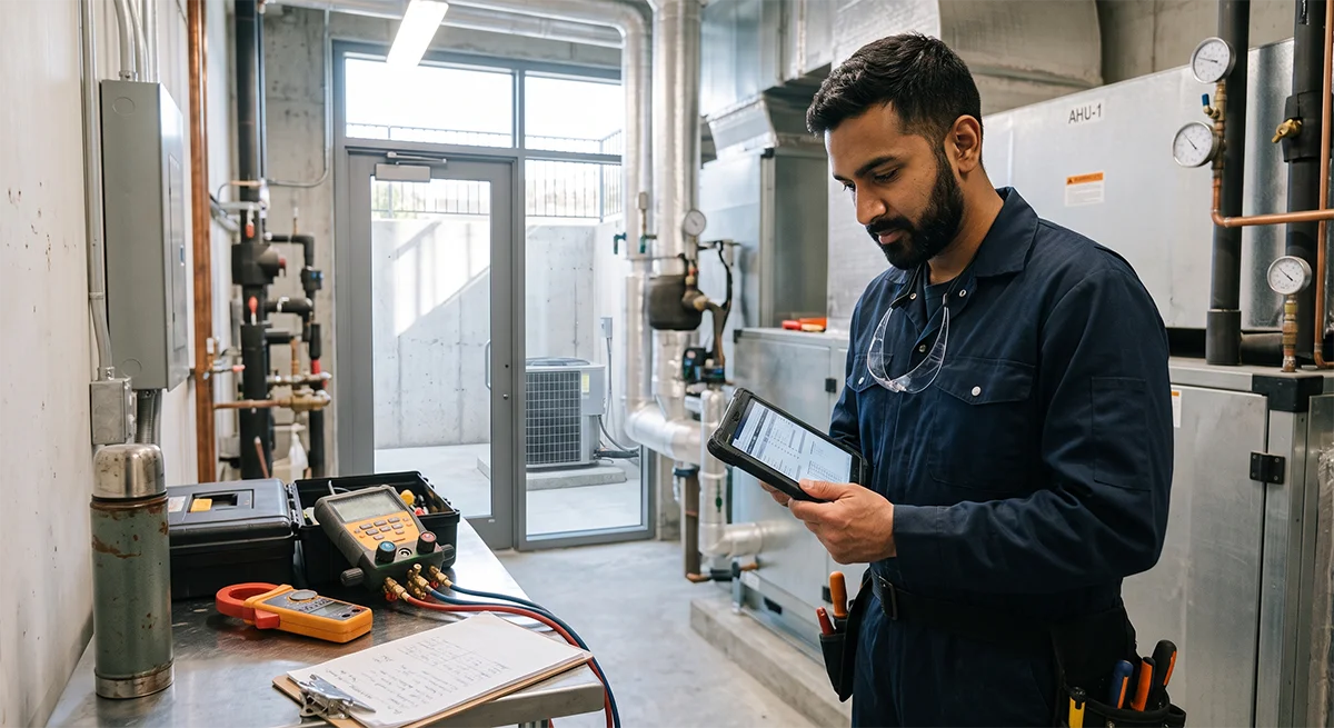
Photos can strengthen the commissioning record. Useful photos include equipment data plates, control settings, static-pressure test locations, instrument readings, condensate piping and the completed installation.
Documentation protects the contractor, helps future service technicians and gives the customer evidence that the system was properly tested.
AC Commissioning Field Checklist
Before leaving the job, confirm that the following work has been completed.
Equipment
- Indoor and outdoor equipment match verified
- Model and serial numbers recorded
- Refrigerant type confirmed
- Metering device confirmed
- Line-set requirements checked
- Equipment clearances verified
Mechanical installation
- Outdoor unit stable and level
- Panels installed correctly
- Refrigerant lines supported and insulated
- Supply and return connections sealed
- Coil and filter inspected
- Service valves open
- Electrical wiring secured
Airflow
- Filter installed correctly
- Blower settings confirmed
- Total external static pressure recorded
- Cooling airflow verified
- Supply and return restrictions checked
- Zone operation tested where applicable
Refrigeration
- Manufacturer charging procedure followed
- Indoor and outdoor conditions recorded
- System allowed to stabilize
- Required pressures and temperatures recorded
- Refrigerant-line insulation inspected
- Service caps checked
Electrical
- Voltage checked under load
- Operating current recorded
- Wiring and terminals inspected
- Disconnect verified
- Overcurrent protection confirmed
- Grounding inspected
Cooling performance
- Return-air temperature recorded
- Supply-air temperature recorded
- Indoor humidity recorded
- Outdoor temperature recorded
- Cooling stages tested
- Variable-capacity test mode used where required
Drainage and controls
- Condensate trap inspected
- Drain slope confirmed
- Drain tested during operation
- Condensate pump tested
- Overflow protection tested
- Thermostat configuration verified
- Customer controls reviewed
A Measured System Is a Finished System
Peak summer conditions leave little room for weak airflow, incorrect controls, poor drainage or an inaccurate refrigerant charge.
A proper HVAC commissioning checklist does not replace manufacturer instructions, technician training or correct system design. It creates a repeatable process that reduces missed steps when schedules are busy and cooling demand is high.
For Ontario HVAC contractors, the most useful commissioning process is not the one with the most paperwork. It is the one that proves the system’s performance with actual measurements.
The equipment should not leave commissioning with unexplained readings, untested safety controls or assumptions written where measurements should be.
A system that starts is operational.
A system that has been measured, verified and documented is ready for Ontario’s peak cooling season.